תיאור
Instructions for use of GM328A transistor tester Note:The following functions are all available in English version, some functions are not updated in Ruian version Description: Input voltage: DC 6.8V-12V Working voltage: about 30mA, measured when inputting 7.5V DC voltage Transistor tester control The tester is controlled by a rotary encoder switch, The rotary encoder switch can have a total of 6 operations, short pre, long pre, left rotation, right rotation, hold left rotation, hold right rotation. In the shutdown state, short pre once to turn on the power and start the test. After a test is completed, if the device is not detected. Long pre the switch or the left and right rotary switch to enter the function menu. After entering the function menu, the left or right rotary switch can be selected up and down in the menu item. To enter a function item, short pre the switch once. When you need to exit from a function, pre and hold the switch.
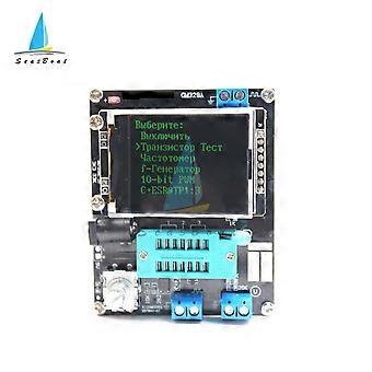
Control button Square wave and PWM outputinterface voltage measurement interface Original test bit In the original test base 160128 full color display Frequency meurement interface Power adapter socket 9V battery contact 9V Work indicator Version function comparison
Features
English
Ruian
Switch off
Yes
Transistor
Yes
f-Generator
Yes
10-bit PWM
Yes
:3
Yes
C+ESR@TP1:3
Yes
1-||-3
Yes
DS18B20
Yes
No
C(uF)-correction
Yes
IR_Decoder
Yes
No
IR_Encoder
Yes
No
DHT11
Yes
No
SelfTest
Yes
Voltage
Yes
FrontColor
Yes
No
BackColor
Yes
No
Showdata
Yes
Test device The tester has 3 test points, TP1, TP2, TP3. The distribution of these three test points in the test block is as follows:
On the right side of the test seat is the test position of the patch component, there are numbers 1, 2, and 3 respectively, each representing TP1, TP2, and TP3 When testing a component with only 2 pins, the pins are not divided into the test order, 2 pins are arbitrarily selected for 2 test points, and the device pins with 3 pins are placed in three test points respectively, regardle of the order. After the test, the tester automatically recognizes the pin name and test point of the component, and displays it on the screen. When testing a component with only 2 pins, if two test points TP1 and TP3 are used, it will automatically enter the continuous test mode after the test is completed, so that the components on TP1 and TP3 can be continuously and synchronously measured without preing the switch. If you are using the "TP1 and TP2" or "TP2 and TP3" test, only test once. To test again, pre the switch once. Before testing the capacitor, discharge the capacitor first, and then insert the test socket for measurement, otherwise the single-chip microcomputer of the tester may be damaged. 1. Calibration The tester calibration is used to eliminate the errors of its own components and make the final test results more accurate. Calibration is divided into quick calibration and full-function calibration. The operation method of quick calibration: short-circuit the three test points TP1, TP2, and TP3 with wires, then pre the test button while observing the screen. The color of the screen will change to black and white. After the prompt meage "Selftest mode..?" appears, pre the test button to enter the quick calibration proce; if the prompt meage "Selftest mode..?" appears, 2 seconds If there is no button in the clock, a normal test proce is performed, and finally the resistance value of the three test points of TP1, TP2 and TP3 is displayed. After entering the quick calibration proce, some data will appear on the screen, just ignore it. Wait until a flashing string appears on the screen After "isolate Probes!", remove the wires that short-circuit TP1, TP2, and TP3. After the character string "Test End" appears on the screen, the quick calibration is completed. When calibrating for the first time, use the full-function calibration method. Full function calibration needs to be entered from the function menu, and a 220nf capacitor is also required. The full-function calibration performs a more comprehensive calibration proce and will take longer. After entering the function menu, rotate the test button to the menu item "Selftest", and then pre the test button to enter the full-function calibration proce. The flashing string "short Probes!" appears on the screen, which is the same as the quick calibration. Use wires to short-circuit the three test points and wait for the calibration proce to proceed. When the flashing string "isolate Probes!" appears on the screen, remove the wires that short-circuit the three test points and continue to wait for the calibration proce to proceed. When the character string "1-||-3> 100nf" is output, install the prepared 220nf capacitors on the test points TP1 and TP3. Wait until the screen prompts "Test End", the full-function calibration proce is comp
-
מותג:
Unbranded
-
קטגוריה:
מדי חשמל
-
גוֹדֶל:
Russian and Case
-
מזהה Fruugo:
237406985-508754190
-
EAN:
9146320786178